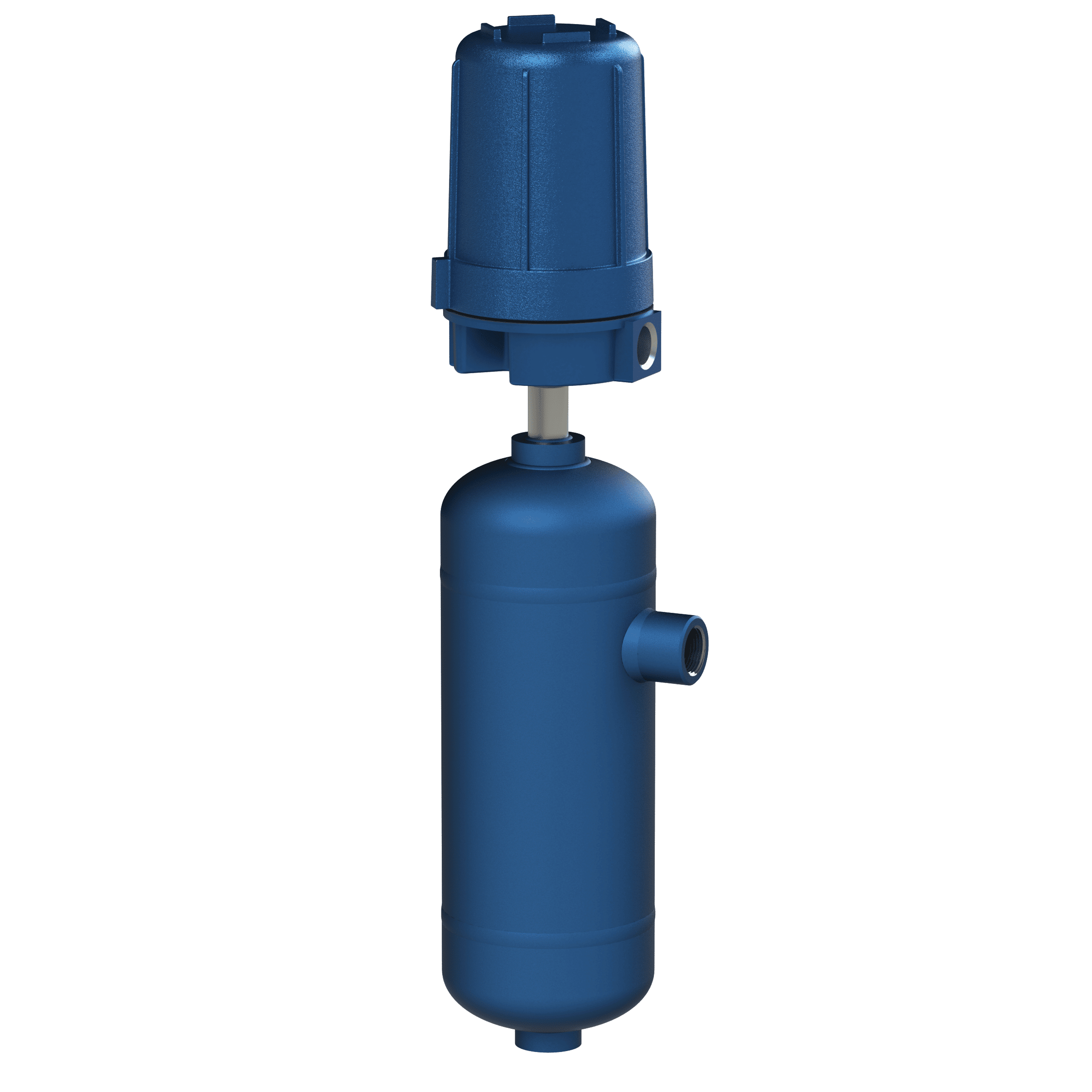
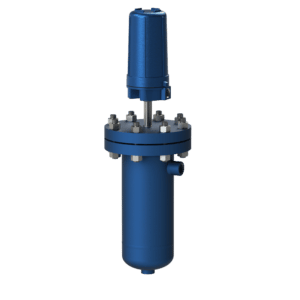
Float Switch, External Cage, Vertical, Two Point, Wide Spacing
The Model 767 Float Switch provides two point alarms with from 6 to 72 inches of elevation spacing between the two switching points. The float features an extra wide spacing between the liquid level positions at which switch action occurs. The wide spacing is accomplished by allowing the float to slide on the float rod. No switch action occurs as long as the liquid level is varying between stops. The float is carried against a stop when it rises or falls far enough. The float pushes against the stop and causes switch action to occur. A counter spring offsets the weight of the attractor, rod, and inner works. The attractor is held in the middle of its travel as long as the liquid supporting the float between stops. The weight of the float pulls the attractor down on low level and its buoyancy lifts it up on high level. Each of these movements produces a switch action. The 767 provides two switch points at widely spaced alarm point locations.
Options: The Model 767 Option D utilizes a differential device and one switch station. It provides pumping control between the high and low switching points. The switch magnet is attracted and the switch station actuates when the upper stop is lifted by a float. The station stays actuated until the level drops enough for the float to push the lower stop down. The attractor is pulled away from the switch magnet; the switch deactivates, and stays that way until the upper stop is lifted again.
Features
- 2 alarm points and/or differential
- Two switch point stations
- Vertical mounted between process connections
- Customizable spacing
Specifications
- Wetted Materials: 304 Stainless Steel, 316 Stainless Steel, carbon steel
- Switch Action: 2 alarm points and/or differential
- Differential: ≤ 72 in (1.83 m)
- Specific Gravity: 0.40 to 2.40
- Temperature:-20 °F to +750 °F (-29 °C to +399 °C)
- Pressure: -15 psig to 2200 psig (-1 bar to +151.7 bar)
- Optional Drain:0.75 in NPT
- Orientation: Side/Bottom, Side/Side, Side/Side/Drain
- Socket Welded Process Connection:1.0 in
- Threaded Process Connection: 1.0 in FPT to 2.0 in FPT
- Flanged Process Connection: 1.0 to 2.0 in
- Flange Rating: ≤ 600 lb ANSI flanges or Grayloc® hub DIN or JIS equivalents
Certifications & Approvals
- Third Party Listed by CSA NRTL/C (USA and Canada) Class I, Division 1, Groups B, C and D; Class II, Division 1, Groups E, F and G; Class III, Division 1 Class I, Zone 1, Ex d IIB+H2 Class I, Zone 1, AEx d IIB+H2
Required Ordering Information
- Detailed model number
- Tag or nameplate detail (if required)
- Documentation/testing tiers (if required, refer to Additional Resources in the product catalog)
- Process fluid or material name
- Process fluid or material dieletric constant
- Maximum process temperature
- Maximum process pressure

